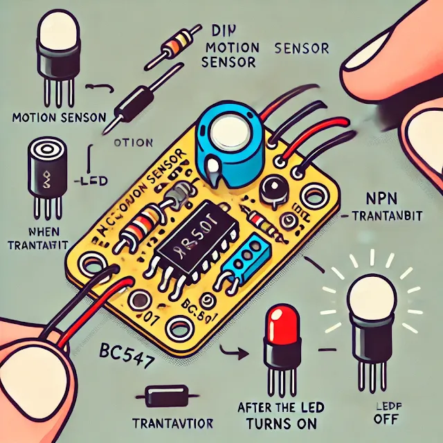
Project 4: DIY Motion Sensor Light
Objective:
To build a motion-activated LED light using a PIR (Passive Infrared) sensor that turns ON when motion is detected and turns OFF automatically after a few seconds.
Components Required:
- PIR Motion Sensor (HC-SR501)
- NPN Transistor (BC547)
- Resistors – 330Ω
- LED – Any color
- Battery – 9V
- Relay Module (for controlling high-power devices)
- Diode – 1N4007 (for relay protection)
- Breadboard & Connecting Wires
Circuit Diagram:
(You can design the schematic using Tinkercad, Fritzing, or any circuit design tool.)
Step-by-Step Instructions:
Step 1: Connect the PIR Sensor
- The PIR sensor has three pins:
- VCC → Connect to +9V (or 5V).
- GND → Connect to ground (-).
- OUT → Connect to the base of BC547 transistor via a 330Ω resistor.
Step 2: Connect the Transistor
- The collector of the BC547 transistor connects to the negative leg of the LED.
- The emitter connects to ground (-).
Step 3: Connect the LED or Relay
- The positive leg of the LED connects to +9V via a 330Ω resistor.
- If using a relay module, connect it to control AC appliances like a bulb or fan.
Step 4: Power the Circuit
- Connect a 9V battery or 5V adapter to power the circuit.
How It Works:
- When motion is detected, the PIR sensor sends a HIGH signal to the transistor.
- The transistor activates, allowing current to pass through the LED or relay, turning it ON.
- After a few seconds (adjustable via the PIR sensor’s delay knob), the LED turns OFF automatically.
Customization Ideas:
💡 Adjust PIR Sensitivity: Use the PIR module’s sensitivity knob to control the detection range.
💡 Use an Arduino: Add an Arduino board to program advanced features like timers or day/night detection.
💡 Control High-Power Devices: Use a relay module to automate home lights, fans, or alarms.

,%20an%20NPN%20transistor%20(BC547),%20a%20resistor,.webp)

Comments
Post a Comment